Monitoring energy at United Biscuits
- Like
- Digg
- Del
- Tumblr
- VKontakte
- Buffer
- Love This
- Odnoklassniki
- Meneame
- Blogger
- Amazon
- Yahoo Mail
- Gmail
- AOL
- Newsvine
- HackerNews
- Evernote
- MySpace
- Mail.ru
- Viadeo
- Line
- Comments
- Yummly
- SMS
- Viber
- Telegram
- Subscribe
- Skype
- Facebook Messenger
- Kakao
- LiveJournal
- Yammer
- Edgar
- Fintel
- Mix
- Instapaper
- Copy Link
Posted: 3 May 2005 | Dr Rob Rolston, Thermal Process Development Manager and Geoff Townsend, Process Technology Controller, United Biscuits Ltd | No comments yet
We are all increasingly aware of the rising cost of energy – both personally and professionally – and the need to conserve it. However, accurate measurement of energy is equally important for the effective control of our heating and cooling processes, as well as the consistency and quality of the final product. This article presents a method that accurately measures energy levels within the process, interprets the results for increased efficiency and uses the technique to solve problems.
We are all increasingly aware of the rising cost of energy – both personally and professionally – and the need to conserve it. However, accurate measurement of energy is equally important for the effective control of our heating and cooling processes, as well as the consistency and quality of the final product. This article presents a method that accurately measures energy levels within the process, interprets the results for increased efficiency and uses the technique to solve problems.
We are all increasingly aware of the rising cost of energy – both personally and professionally – and the need to conserve it. However, accurate measurement of energy is equally important for the effective control of our heating and cooling processes, as well as the consistency and quality of the final product. This article presents a method that accurately measures energy levels within the process, interprets the results for increased efficiency and uses the technique to solve problems.
By far the widest use of the technology has been within the baking process.. Any baking process must achieve the following objectives:
- The correct size, appearance and texture of product desired
- Enabling the Maillard reactions to proceed correctly and hence produce flavour, colour and aroma development
- The removal of moisture in a controlled way – this is all-important to biscuit makers
Each of these are achieved by the transfer of heat and so all require precise control of energy input. However, nothing can be accurately controlled unless it is first measured and the accuracy of measurement is all-important.
This is why United Biscuits (UB) has put so much effort in recent years into measuring energy within processes. We have experienced benefits in each of the following areas: Plant output; transferring product across lines; troubleshooting; reducing biscuit checking and reducing waste that might occur at breaks in production when ovens must be closed down and then restarted. The question of environmental cost-avoidance is also raised and energy-measurement has been applied to cooling as well as heating processes.
The following provides some useful background information on the use of heat flux techniques to measure the heat energy transfer within an oven.
There are three primary modes of heat transfer within an oven: conduction, convection and radiation. They all occur at some level in an oven, but the actual proportions are dependent upon the oven type and the conveyor type.
Conduction
At a molecular level, conduction represents the transfer of energy through the collisions caused by the vibration of the more energetic molecules at higher temperatures with adjacent less energetic, lower temperature molecules.
The heat flux (Q) is linearly dependent upon the temperature difference (T1 – T2) across the body and the thermal conductivity of the body (k). It is also inversely proportional to the thickness of the body.
Convection
This is heat energy transferred from a fluid to a solid surface as a result of the bulk movement of the fluid across the surface.
In this case the heat flux (Q) is directly proportional to the temperature difference (T1 – T2) and the convection coefficient (h). The latter is primarily a function of the velocity of the fluid flow. The higher the air velocity, the greater the rate of heat transfer.
Radiation
For radiant heat transfer, the whole process is quite different. Instead heat is transferred by electromagnetic waves in the same way as light travels, but at a slightly different wavelength. As a result the governing equations are much more complex.
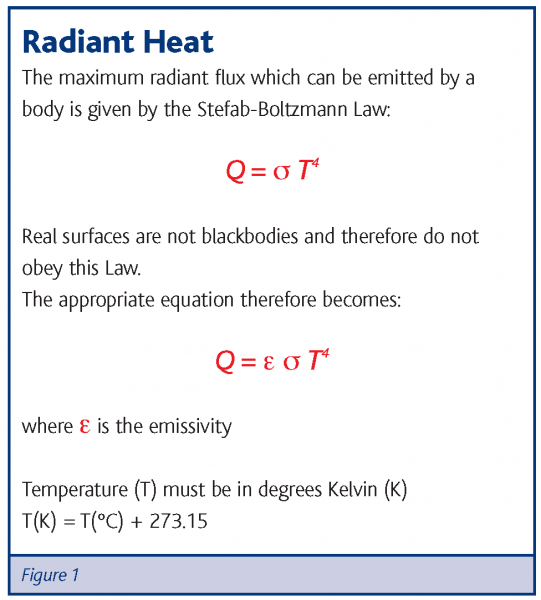
The radiant heat emitted by a surface depends upon the absolute temperature (in Kelvin) raised to the power of four. This, in effect, means that doubling the temperature of a radiant heat source will increase the radiant heat output by a factor of 16. This means that radiant heat sources are much more sensitive to temperature changes than conductive or convective heat transfer.
The surface condition also has a marked effect upon the radiant heat emitted. This is controlled by the emissivity of the surface. A perfect ‘blackbody’ radiator has the maximum emissivity of one. A poor radiator such as polished aluminium may have an emissivity of less than 0.05, i.e less than 5 per cent of a perfect surface. Interestingly, the inner surfaces of baking chambers in many ovens are coated with an aluminium-based layer!
Oven types
There are many types of tunnel ovens available and the more common variations will be discussed. One important feature to consider is whether the oven is:
- Direct-fired – with the products of combustion from the burner sharing the baking chamber with the product
- Indirect-fired – where the baking chamber atmosphere is kept separate from burner combustion products
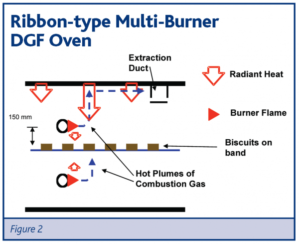
One of the most common oven types are the multi-burner units, usually direct-fired but occasionally indirect. These ovens use a ribbon-type burner mounted transversely above and below the band (Figure 2).
Above the band the hot plume of gas originating from the burning flame will rise rapidly, due to buoyancy effects, heating the roof above by natural convection. The hot roof then re-radiates the heat back down the product on the band.
In the case of the bottom burners, the base of the biscuit and/or the band is heated by the natural convection plumes from the burner flame.
The overall heat output for this oven will depend upon the number of burners in operation and the amount of gas supplied to each burner.
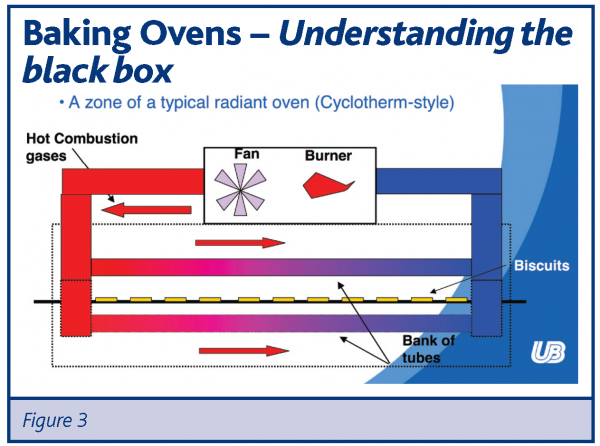
Indirect-fired radiant ovens are usually of the Cyclotherm variety (Figure 3). In this case the heat in each zone is supplied by one large main burner and the hot combustion products are circulated through banks of radiator tubes positioned above and below the band. One disadvantage of these ovens is the non-uniform heat flux along the zone. As the combustion gases lose temperature, so does the tube surface which results in a rapid decline in heat flux.
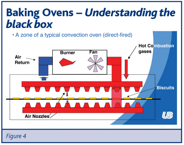
Forced-convections can be either direct or indirect-fired. In this direct-fired example, the hot combustion gases are mixed with the recirculation airflow prior to its injection back into the oven chamber (Figure 4).
On this impingement-type system, banks of air nozzles above and below the oven band direct jets of air onto the product. This is a very effective airflow arrangement and results in a high value for the convection coefficient (or H value). The recirculation dampers on these ovens control the overall airflow rate and the level of the convection coefficient. This provides two methods to alter the overall heat flux level, either by adjusting the temperature of the hot air or using the recirculation dampers to control the airflow.
Why is heat flux measurement so effective?
Heat energy is the primary driver of the changes that occur inside the oven and, hence, represents the fundamental process measurement.
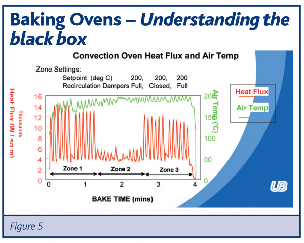
On a forced-convection oven, the air temperature is only one of the drivers controlling the overall heat flux in the oven. The airflow rate in each zone, as controlled by the recirculation dampers, is equally important as shown in Figure 5.
This example relates to a three-zone forced-convection oven. The air temperature in each zone has been set to 200°C. The recirculation dampers in Zones 1 and 3 have been set to maximum and Zone 2 has been set to minimum. The heat flux profile shows the expected result with a much lower overall heat flux in Zone 2. In comparison, the air temperature profile provides no indication of the substantial differences in heat flow between zones.
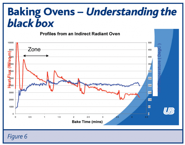
On a radiating oven the air temperature is of even less value. In this oven the source of the heat is the roof of the baking chamber and, hence, the roof temperature profile should be measured along the oven – not the air temperature profile. Figure 6 shows an example of indirect-radiant Cyclotherm oven, as described earlier.
The radiant tubes are at their hottest at the start of the zone, producing the maximum heat flux level. As the hot gases travel along the tubes they cool down which causes a declining heat flux profile. In comparison the air temperature profile along the baking chamber does not provide any indication of the real variation in heat.
Applications of heat flux
Optimising plant output
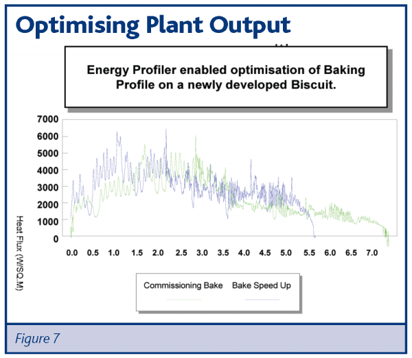
A new cream-biscuit product, based on a semi-sweet biscuit shell, was originally introduced with a 7.5 minute bake time. Following a successful launch a throughput increase of 25% was required. Using the original heat flux profile as base-line, we maximised the heat flux levels in Zone 1 to give the maximum lift in this section. Later in the profile the heat flux level was increased to speed-up the final moisture removal and colour development and achieve the required reduction in bake time.
Reducing biscuit checking
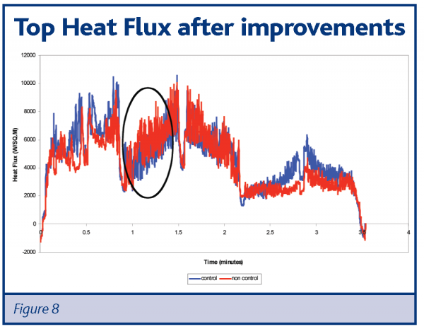
This example is related to biscuit checking – the spontaneous breakage of product after baking due to the build-up of internal stresses following the internal re-distribution of the moisture still remaining after baking. In this case, product on one side of the band appeared more susceptible than the other. An investigation of the cross-band heat flux profiles indicated a significant difference of heat flux within Zone 2.
On this particular forced-convection oven, the airflow was delivered into each zone by 11 longitudinal tubes mounted above (and below) the oven-band. Splitter plates were used to control the flow to each tube. The position of the increased air-flow area coincides with the higher heat flux levels.
The solution was quite straight-forward: remove the blanking strips from the flow-splitter, as originally fitted by the oven manufacturer during commissioning. The improvement in Zone 2 is quite significant (Figure 8). This effect can only be detected using heat flux profiling, as the cross-band temperature profile was quite uniform. The problem was caused by airflow variations.
Reducing waste after production breaks
On this line there was a very complex secondary process that stopped quite frequently – sometimes for long periods. This naturally involved stopping the oven, but a proper stoppage procedure had not been established and the oven frequently overheated quite badly. This resulted in significant waste on re-starts that averaged more than £3000 per day.
The solution was to monitor the oven energy levels with and without production, in order to identify new, more suitable settings for no-product operation. As a result we were able to reduce waste resulting from an overheated oven by two-thirds, providing an annual saving of £200,000.
Product transfers
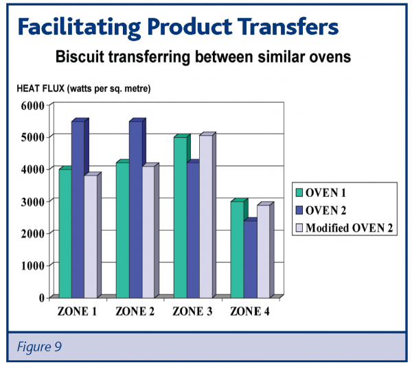
In this example (Figure 9) the objective was to transfer production between two ovens. Initially no problems were foreseen as they were effectively identical ovens from the same manufacturer, of similar age and specification. However, the product from Oven 2 was markedly different and a subsequent comparison of heat flux profiles explained the reason. Further investigation identified the cause as uprated burners in Zones 1 and 2 that had not been recorded at the time of implementation. With this information it was now a relatively straightforward process to revise the burner output settings and obtain the required heat flux levels.
Cake oven
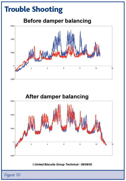
This example refers to an oven making cake-bases for a dessert product (Figure 10). There was a significant variation in product quality between both sides of this wide oven band. The heat flux profiles show a considerable difference in heat flux across the band. Investigation of the controls on this wide, forced-convection oven identified that it had separate recirculation damper controls for each side of the oven. Unfortunately, one side of the oven had become a storage area for racking and the controls were inaccessible. With time, the existence of the controls had been forgotten.
The cross-band balance was easily resolved once the other controls were accessible.
Cooling tunnel
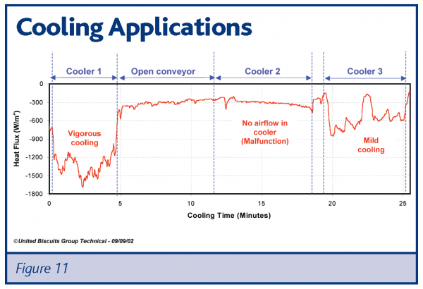
This example shows the cooling profile on a secondary-process cooling tunnel (Figure 11). The tunnel has three cooler sections and one section of open conveyor. Although the standard instrumentation on each zone indicated that the cooling tunnel was performing satisfactorily, the heat flux profile showed a completely different picture.
The large negative heat flux in Cooler 1 is indicative of vigorous cooling. However, there is clearly a problem in Cooler 2 as its performance is no better than the open conveyor section. The performance of Cooler 3 was also below par. Without the use of heat flux, this system could have continued under-performing for some considerable time. Also, the use of heat flux enables us to focus much more quickly on the problem areas.
Energy saving and the future
The demands upon energy saving as a result of the Kyoto protocol and the Climate Change Levy are forcing the baking industry to address the efficiency of their processes more effectively. Energy profiling is an essential tool in this process, identifying energy-wasting problem areas, optimising the energy used to deliver the correct baking conditions and helping to maintain quality and performance during any energy-saving exercises.
Examples of these exercises include:
- Optimising the use of convection or turbulence systems
- Reducing extraction
In the first example, increasing the recirculation airflow levels in the convection system will allow the oven to be operated at lower air temperatures, reducing heat losses both up the exhaust flues and through the oven walls.
Reducing extraction rates will also conserve energy by reducing the excess cold air drawn into the oven, which is heated and then exhausted up the flues. The effect of the reduced extraction will be to increase both air and surface temperatures within the oven. Heat flux is essential to ensure the correct baking conditions for the product are maintained by reducing the energy input, usually gas, by the appropriate amount.
Conclusion
UB has used this technology now for more than a decade across many different ovens, products and processes. We remain committed to the benefits obtained by the use of this technology and are very satisfied with the accuracy, reproducibility and general user-friendliness of the system.
